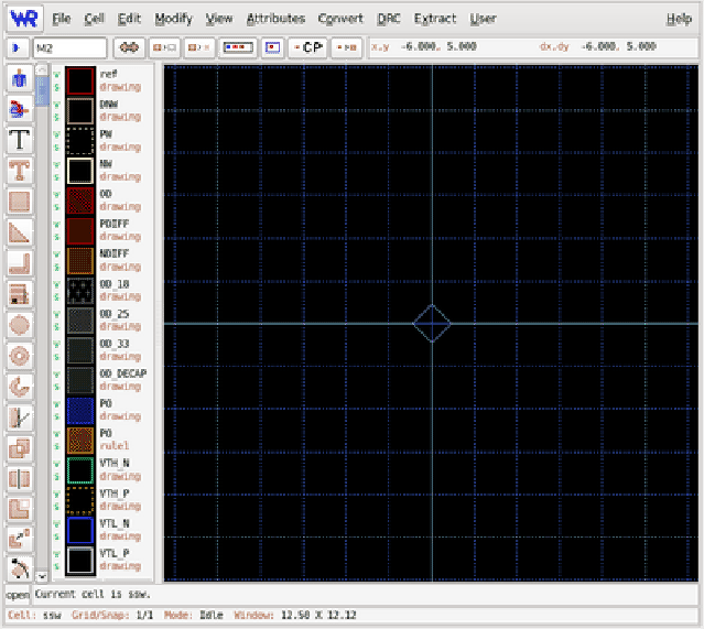
Figure 3.1 shows a view of the Xic graphical user interface. There is generally a single large window present when Xic first starts. The window can be repositioned, and the size of the window can be adjusted through the window manager methods.
The column of buttons along the left is the ``side menu'' and is visible when the current cell is being edited. To the right is the scrollable layer table, which displays the layers supported by the process. If the XIC_MENU_RIGHT variable is set in the environment when Xic starts, the layer table and side menu will be located along the right of the window. If the XIC_HORIZ_BUTTONS environment variable is set, the ``side menu'' buttons will actually be arrayed across the top of the window. The side menu is only displayed when editing. The layer table may also be invisible, as the user has this option.
The ``top menu'' contains buttons and other controls and displays, located near the top of the window, below the main menu bar. The prompt line, where the user interacts textually, is just below the main drawing window. To the left of this is the ``keys pressed'' area. Below this is the status line, which displays information about the program state.
These features will be fully described in the sections that follow.
Xic has eleven drop-down menus, arrayed in a menu bar which extends across the top of the main application window.
| File Menu | Commands to open, save, and list files and cells. This menu also contains the printer interface. |
|---|---|
| Cell Menu | Commands to access and manipulate the database of cells in memory. |
| Edit Menu | Commands which are used to modify the current design. |
| Modify Menu | Supplemental commands for layout modification. |
| View Menu | Commands which affect the presentation of the current design, including the selection of physical and electrical (schematic) modes. |
| Attributes Menu | Commands which affect the presentation of the design, such as the colors used. |
| Convert Menu | Commands for importing and exporting designs to various non-native file formats. |
| DRC Menu | Commands associated with design rule checking. |
| Extract Menu | Commands associated with the extraction of electrical information and netlists from the physical layout, and layout versus schematic checking. |
| User Menu | The script debugger, and the buttons that correspond to user-generated scripts. |
| Help Menu | Documentation and the entry into the help system. |
If the mouse button is stationary over a menu button for a second or two, a ``tooltip'' will appear. This is a transient window that contains a sentence describing the function of the command. This also provides the internal name for the command. Every command has an internal name of five characters or fewer. This name can be used as a keyboard accelerator, and as back-door input to the help system. The help keyword for the command is ``xic:'' followed by the command name, for example ``xic:prpty''. Typing a question mark (`?') into Xic followed by the keyword will display the help text for the command.