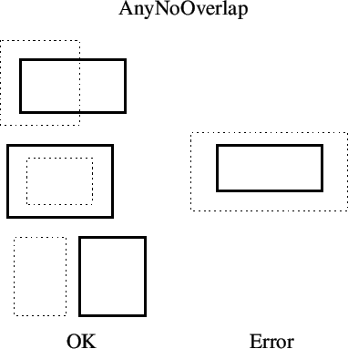
next up previous contents index
Next: MinEdgeLength Rule Up: Built-In Design Rules Previous: MaxArea Rule   Contents   Index

Edge Rules

In the discussion to follow, the ``source'' is the material of the object being checked, either a layer (on which the rule is defined) or a layer expression result if the Region specification is given. The ``target'' is the set of figures associated with the expression supplied to the rule, for those rules that take an expression.

The rules described in this section are ``edge tests'' where the region of interest is generally a small constructed area along an edge. The test is applied for each applicable edge portion of each source figure. The constructed area is rectangular, parallel to the source figure edge, and may extend out of the source figure, or into the source figure. These extend only along the parts of the source figure edge where certain conditions apply, as will be described. The width of the test area (perpendicular to the figure edge) is the dimension associated with the rule.

We find the edge portions of a source figure as follows. We iterate through the edges. For each edge, we construct a unit-width test area that extends outside of the figure. We throw out the parts of the edge where the test area intersects ``source compatible figures'', meaning the same layer or layer expresion as the source. Thus we throw out the part of the edge which is not really an edge, but a boundary between dark areas of the same type and is therefor not a physical discontinuity. The resulting edge portion is the starting point for further restrictions that are rule-specific.

Below is a table which identifies the edge portions identified for the built-in rules, and the test performed.

rule where test src out trg in trg out
MinEdgeLength in len u c c
MaxWidth in snf u    
MinWidth in sf u    
MinSpace out se u    
MinSpaceTo out te u u x
MinSpaceFrom out tf u c x
MinOverlap in tf u c x
MinNoOverlap in te u u x

The first column specifies the built-in rule name of the ``edge'' rules. These will be described in more detail below. The where column indicates the direction of the constructed test area along a source figure edge, either projecting into the figure or outside of the figure. The test indicates the type of test to perform in the constructed area. These are

len
Measure the edge length and compare to given dimension.
snf
The test area is not fully covered by source-compatible material.
sf
The test area is fully covered by source-compatible material.
se
The test area contains no source-compatible material.
tf
The test area is fully covered by target-compatible material.
te
The test area contains no target-compatible material.

The three remaining columns indicate the part of the source figure edge that is used to construct the test area. These indicate the required coverage of the source material just outside the edge, and target material just inside and just outside of the edge. The possibilities are

c
Covered by the material.
u
Not covered by the material.
x
Doesn't matter.

So, for example, for MinSpaceTo, we take the part of the edges that are not covered by source just outside of the edge, and not covered by target just inside of the edge. The test will pass if the constructed area, which extends out of the figure, intersects no target material.

Each of the ``edge'' rules recognize two additional keywords:

Outside layer_expr
This will apply when identifying the part of the edge of a source figure to use when constructing test areas. The given layer expression must be dark along the edge just outside of the figure, in the parts of the edge to use for the test area. This provides an additional rather arbitrary constraint on the test area construction which may be of use in some cases.

Inside layer_expr
This is very similar to the Outside constraint, but applies to the side of the edge just inside of the figure. Only the parts of the edge where the given layer expression is dark just inside of the figure are considered for edges of the test area.

For example:

``The minimum distance to CO from a NP/PP butt edge over OD is 0.06 microns.''

This can be implemented as

PhysLayer NP
MinSpaceTo Region OD Inside !PP Outside PP CO 0.06
PhysLayer PP
MinSpaceTo Region OD Inside !NP Outside NP CO 0.06

The built-in edge rules are described in more detail below. In each, for simplicity we will use the following as an abbreviation for the syntax elements:

EdgeArgs = [Region region_expr] [Inside inside_expr] [Outside outside_expr]


Subsections
next up previous contents index
Next: MinEdgeLength Rule Up: Built-In Design Rules Previous: MaxArea Rule   Contents   Index
Stephen R. Whiteley 2022-05-28